How to Better Print Syntax Tree Structures
What is a Syntax Tree?
A Syntax Tree is a tree-like data structure used to represent the syntactic structure of source code. Each node represents a syntactic construct occurring in the source code. Syntax trees are widely used in compilers and interpreters to help analyze and process the source code of programming languages.
Syntax trees can be further divided into Concrete Syntax Tree and Abstract Syntax Tree. The front end of a compiler typically generates a CST based on BNF grammar and then constructs an AST based on semantics.
To facilitate the use of syntax trees, the Visitor design pattern is usually supported. This allows a custom Visitor to traverse node types of interest.
This raises a question: with so many node types, how can we intuitively visualize this tree structure, especially in C++, which does not support reflection and thus cannot debug to inspect types?
Below are some attempts the author made while developing Lint rules based on the slang project.
Slang is a Modern C++ project that employs many new features from C++17 and C++20.
Slang is a software library that provides various components for lexing, parsing, type checking, and elaborating SystemVerilog code. It comes with an executable tool that can compile and lint any SystemVerilog project, but it is also intended to be usable as a front end for synthesis tools, simulators, linters, code editors, and refactoring tools.
Slang is the fastest and most compliant SystemVerilog frontend.
Before addressing this issue, it’s necessary to provide a brief introduction to SystemVerilog. Then, the syntax tree serialized in JSON format will be presented, followed by the author’s solution for comparison.
Introduction to SystemVerilog
SystemVerilog is a hardware description and verification language (HDVL) that extends the Verilog hardware description language. It combines the features of both hardware description languages (HDL) and hardware verification languages (HVL), aiming to provide a more powerful and flexible tool for designing and verifying digital systems. SystemVerilog was developed by the Accellera standards organization and has been standardized by the IEEE Standards Association as IEEE 1800.
Main Features of SystemVerilog
- Synthesis and Simulation: Supports design synthesis and simulation, allowing the description of hardware circuits and verification of their behavior.
- Object-Oriented Programming: Introduces object-oriented programming concepts such as classes, inheritance, and polymorphism for developing more complex testbenches.
- Advanced Verification Features: Includes many advanced verification features like assertions, constraint randomization, and coverage.
- Interfaces and Modularity: Supports interface and modular programming, promoting the reusability and modularity of designs.
- Parallel Processing: Capable of parallel processing to describe parallel hardware behavior.
- Combinational and Sequential Logic: Supports the modeling of both combinational and sequential logic.
Basic Constructs of SystemVerilog
Module
A module is the basic construct in SystemVerilog, used to define the structure and behavior of a circuit. For example:
1 | |
Interface
An interface is used to define the communication signals between modules. For example:
1 | |
Class
A class is used for object-oriented programming in the verification environment. For example:
1 | |
Applications of SystemVerilog
- Hardware Design: Used to describe the structure and behavior of digital circuits, which can be synthesized into actual hardware circuits.
- Hardware Verification: Provides rich verification features for validating the correctness and performance of digital designs, including functional and formal verification.
- Testbench Development: Can be used to develop complex testbenches for comprehensive hardware design verification.
Advantages of SystemVerilog
- Enhanced Expressiveness: Compared to Verilog, SystemVerilog offers more powerful syntax and semantics for more efficient description of complex hardware and verification environments.
- Efficient Verification Methods: Introduces advanced verification technologies such as constraint randomization, coverage-driven verification, and assertions, significantly improving verification efficiency.
- Object-Oriented Programming: Supports object-oriented programming, making verification code more structured and maintainable.
Overall, SystemVerilog is a powerful and flexible hardware description and verification language widely used in modern digital circuit design and verification.
JSON Format AST Provided by slang
The slang project offers a command-line tool and provides the --ast-json option to serialize the AST into JSON format. Let’s take this adder module as an example:
1 | |
The serialized JSON structure is as follows:
1 | |
At first glance, this JSON format might seem too long because a node can have many attributes. Additionally, the indentation does not make the parent-child relationships clear.
Inspiration from the tree Command
Tree structures are two-dimensional and difficult to display. However, the tree command tool prints tree structures very clearly.
1 | |
This display method clearly shows the parent-child relationships, making it easy to see which files are contained within each directory.
This specific hierarchical tree is known as a directory tree.
Solution Display
Using the same SystemVerilog code:
1 | |
Optimized AST Display
Let’s display the AST using the directory tree method:
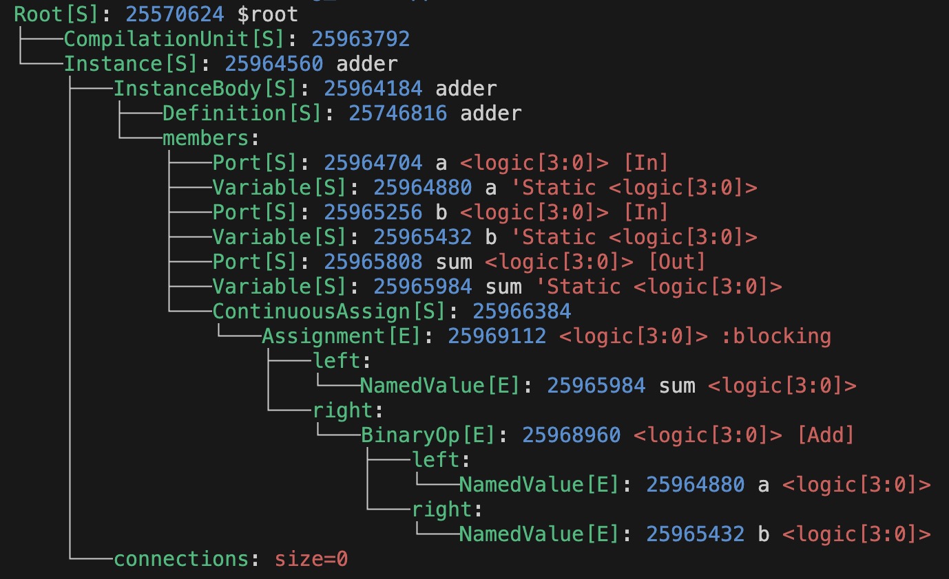
As you can see, each line is a key-value pair separated by a colon. Additionally, term colors are used for differentiation.
The green key represents the class type of the node, and the value part represents the attribute information of the node, separated by spaces.
This allows the AST to be displayed in a compact manner.
Optimized CST Display
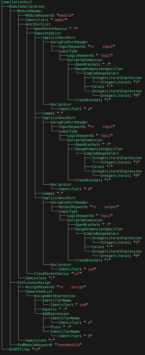
Slang does not provide a command-line method to display the CST, but users may need to access the CST directly for tasks such as formatting SystemVerilog code.
Below is the CST structure of adder displayed in a similar way. You can see that the value of the leaf node is the original text of the node.
Summary
By referring to the directory tree display method and combining key-value pairs with term colors, a more compact and clear syntax tree display method is provided. This method makes it easier for users to develop based on AST and CST.
However, the disadvantages of this method are also clear. It is not suitable for text-based storage and is not ideal for displaying large codes. Of course, JSON format is also not suitable (but both can be constrained by hierarchical paths, displaying only parts of the syntax tree structure).